Table Of Content

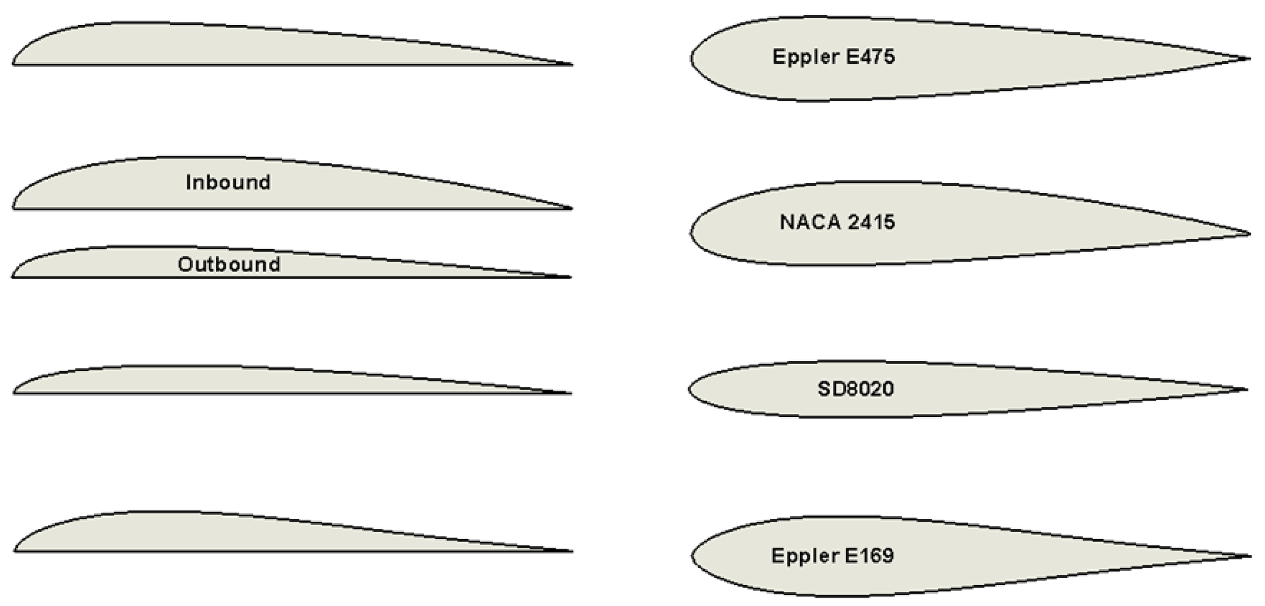
However, for the drag, it is necessary to account for the shear stress because this component is the dominant contribution to the drag at low angles of attack. Sailplanes and some other aircraft use laminar flow airfoils, which are designed to maximize the extent of the laminar boundary layer over the leading edge of the airfoil, hence substantially reducing skin friction drag. A series of airfoils called the FX-airfoils have been designed explicitly for sailplane applications by Franz Xavier “FX” Wortmann, examples being shown in the figure below.
A Complete Guide to Airfoil Shape Considerations
It’s vital to calculate CL at the planned cruise speed, altitude, and gross weight. For most airplanes this will be very different than the value one would get at sea-level condition or at maximum speed. To get the lowest cruise drag, we need to consider the product of wing area times drag coefficient in cruise. The best airfoil/flap combination is the one that meets stall speed requirements and yields the lowest value of wing area (S) times parasite drag coefficient (CDp) at cruise conditions.
Supercritical Airfoils
A further increase in the angle of attack is followed by the onset of flow separation on the upper surface, a sudden loss of lift, and a significant increase in drag; the process is called a stall. The computational tools to help design airfoils that produce specific aerodynamic characteristics first became available in the 1920s. The development of the thin-airfoil theory by Max Munk (in the U.S.) and Hermann Glauert (in the U.K.) during the 1920s led to a better understanding of how the camber affected an airfoil’s lift and pitching moments. It is essential for engineers how to interpret and use two-dimensional airfoil characteristics. To this end, the ability to access, analyze, and use graphs from catalogs of airfoil characteristics is critical.

Pressure & Shear Stress Coefficients
Other NACA camberlines can be examined better to understand the drawing process of NACA airfoil shapes. A supersonic double-wedge airfoil with a thickness-to-chord ratio of 8% is operated at an angle of attack of 5.0 degrees at a Mach number of 3.5. The values of the constants and depend on the exact shape of the airfoil. It can be seen that for the particular airfoil used here, the aerodynamic center location is at 24.25% chord. The location of the aerodynamic center depends on the airfoil section and the Mach number at which it operates.
Understanding the Effects of Airfoil Shape on Lift
Changes to the performance characteristics of an airfoil may be made in seconds. The same concern applies when modifying an existing design to try to improve its performance. A trap more than one modifier has fallen into is when they substitute the new “advanced” airfoil for the one in the original design. Hoping that they will see a performance improvement, they are sadly disappointed when they find their “improved” airplane performs worse than a stock one. Conceptually, relates to the speed of a vehicle in comparison to how fast pressure waves move. These two parameters govern kinematic similarity in fluid dynamics, which drive pressure and viscous forces, which ultimately relate to the aerodynamic force response.

The Advantages of Cambered Airfoils
Getting more into the technical and mathematical side of airfoil design, here are two popular names that you may see when researching airfoil shapes. Reading up about them might be a good way to learn about the nuances of how designers create airfoils. The wing for many types of aircraft is sized by stall speed, which we will discuss in the next section.
Airfoils are designed to function at their best at a specific “design CL.” When choosing an airfoil for an airplane, the design CL is the cruise value. Compare the drag coefficient of candidate airfoils when they are at this design lift coefficient to find the one that has the lowest drag at the actual cruise condition of the airplane you are designing. With over a century of airfoil shape designs created, there is a wealth of research and actual flight performance information available that can be leveraged when designing airfoil shapes.
Wind tunnel experiments can validate these predictions, providing empirical data for any design changes and aerodynamic refinement of the airfoil section. Subsequent flight testing may give further assessments as to the validity of the selected airfoil(s), allowing engineers to iteratively refine airfoil designs based on actual aircraft performance. Throughout this process, considerations specific to the intended application must be integrated to ensure that the optimized airfoil shapes meet the unique requirements of particular flight vehicles.
Owl Wing Design Reduces Aircraft, Wind Turbine Noise Pollution - AIP Publishing LLC - AIP Publishing News
Owl Wing Design Reduces Aircraft, Wind Turbine Noise Pollution - AIP Publishing LLC.
Posted: Tue, 18 Jan 2022 08:00:00 GMT [source]
Lift as an Equation:
The favorable pressure gradients tend to give the airfoils lower drag than other airfoils, at least over a limited range of attack angles. Unfortunately, surface contaminants or other transition-causing disturbances quickly spoil the characteristics of laminar flow types of airfoils, sometimes resulting in significant adverse characteristics. As shown in the following figure below, the critical length dimension of an airfoil profile is defined in terms of its chordline; the chord is defined as the distance measured from the leading edge of the airfoil profile to its trailing edge. Some of the earliest known airfoil sections considered for aircraft concepts were patented in the 1880s by Horatio Phillips, as shown in the figure below, which were inspired by the wings of birds. Taking inspiration from nature is nothing new in engineering, but history shows that it should not necessarily be a basis for our engineering. Notice the thin, highly cambered profile shapes, which are now known to have poor aerodynamic efficiency compared to modern airfoils, at least under the operating conditions of most flight vehicles.
There has recently been much interest in designing efficient airfoils for use at the very low flow speeds and low Reynolds numbers found on UAV systems. These require detailed knowledge of boundary layer developments, including laminar to turbulent boundary layer transition. Unfortunately, airfoil characteristics at low Reynolds numbers are usually quite different from those at higher Reynolds numbers, often showing remarkably low aerodynamic efficiencies.
The main objective is to reduce as much as possible the sum of the squares of the differences or residuals between the fitted straight line and all of the data points, as shown in the figure below. CH-750, the Cessna 210 Centurion, and the General Dynamics F-16 Fighting Falcon. If that doesn't give you what you need you can also check out the UIUC Airfoil Coordinate Database or airfoiltools.com.
You may now be wondering how engineers go about designing or specifying an airfoil. NASA/NACA, among others, has completed a LOT of work designing, parameterizing and creating a library of airfoil sections that are often used (or used as a starting point) when designing a new aircraft. Thankfully, there are a number of references on the internet where you can go and download the coordinate geometry for just about any airfoil you may want to view or use.
Since thepressure gradient increases with an increasing angle of attack, the angle of attack shouldnot exceed the maximum value to keep the flow following the contour. If this angle isexceeded, however, the force keeping the plane in the air will decrease, and may evendisappear altogether. Another way of drawing an airfoil section graphically is to draw it as a series of circles of radius (or ) if done non-dimensionally as a fraction of chord) centered on the camberline, as shown in the figure below. The upper and lower surfaces of the airfoil are then formed from curves drawn tangential to all of the circles. The linearized theory shows that the lift coefficient is independent of the airfoil shape.
No comments:
Post a Comment